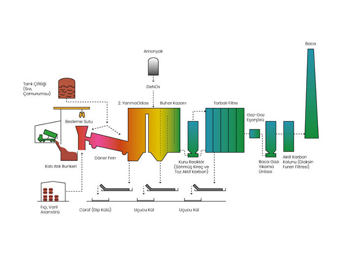
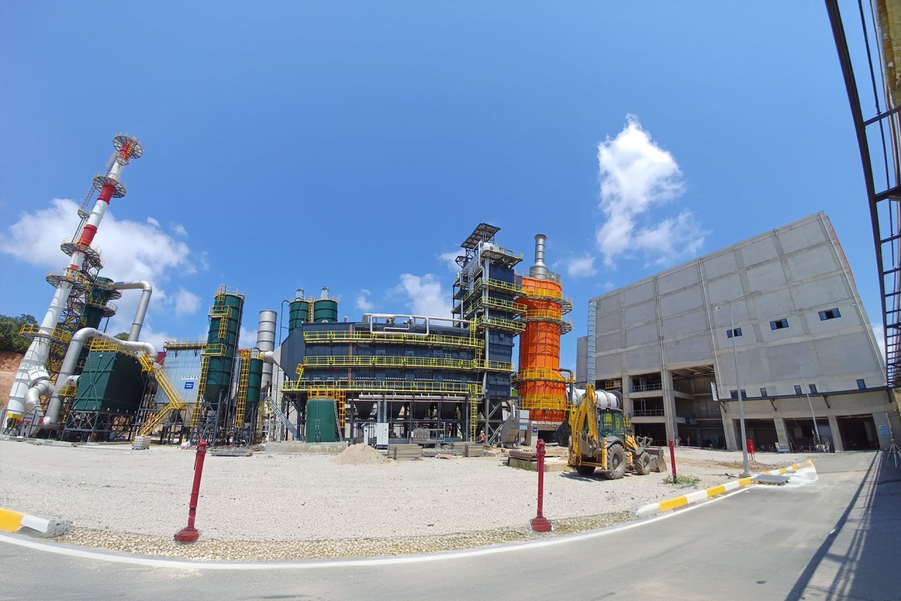
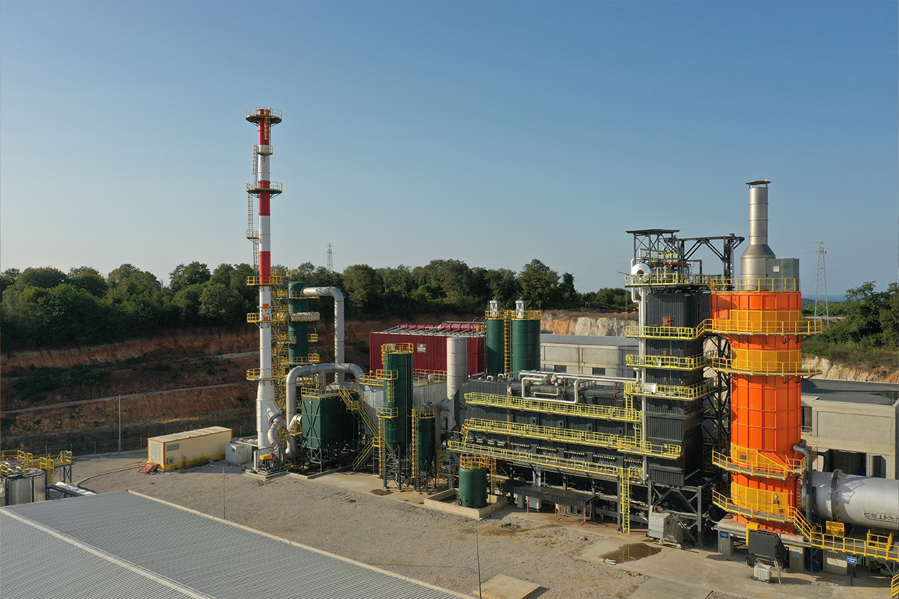
Our Facility

Home / Our Facility
Our FacIlIty

Our Industrial Waste Thermal Disposal Facility

This facility, with an annual incineration capacity of 33,000 tons of industrial waste,
plays a significant role in environmental management.


Some of the waste accepted into the facility includes halogenated and non-halogenated organic liquid
solvents, refinery bottom liquids, mercaptan, isocyanates, PCB-containing transformer
oils, high-odor wastes like CTC, packaged chemicals used as raw materials,
packaging waste contaminated with hazardous chemicals,
chemical-absorbed wipes or absorbent materials, expired
medications, raw materials, cosmetics, agricultural chemicals, waste
containing residues of dangerous substances that can react, whether odorless or pungent.


The declaration, labeling, transportation, and disposal of the waste accepted into the facility
are carried out in accordance with the relevant regulations of the Republic of Turkey's Ministry of
Environment, Urbanization, and Climate Change.


With the energy obtained from the waste processed under R1 recovery operations,
we produce 5.6 MW, which meets the electricity needs of 15,000 to 20,000 households.


Main Sections of the Facility

The building consists of 4 (3+1 - unloading cassette after the separator) cassettes, which are transferred to the loading mouth with the help of a crane, where the maximum loading is monitored for control purposes with a weighing system. When the incinerator temperature reaches a sufficient level for loading waste, the first of the closed guillotine lids allows the desired amount of waste to advance by weighing. When the waste reaches the second guillotine lid, the first one closes. Then, the second guillotine opens, and the waste is transferred to the rotary furnace. The movements of these guillotine lids are operated through a Hydraulic Unit.

Packed (plastic or metal barrels, cardboard, IBC, etc.) waste is taken to the barrel storage area. The barrel storage area has a roofed upper section and a concrete structure made leak-proof. In the barrel storage area, spills and washing waters are collected in the underground reservoir through a grid system and undergo laboratory analysis.

Liquid waste is collected here according to its chemical content. There are five liquid waste mechanisms, four of which feed into the rotary furnace, and one into the secondary combustion chamber. Operators can adjust the waste amount through the flow meters on the liquid lines. Liquid waste is pulverized before being fed into the system. This is to increase the surface area that will be affected by the heat inside the furnace and to accelerate combustion. Thanks to this process, the surface area on which heat will act on the liquid waste increases, and combustion speeds up.

There are a total of 12 tanks with a capacity of 45 m3 in the tank farm.

  • 2 solvent tanks.
  • 2 fuel oil tanks.
  • 1 special liquid (chlorine %1) tank.
  • 1 sludge liquid tank.
  • 2 flammable (DKD) liquid tanks.
  • 2 waste oil (YKD) liquid tanks.
  • 2 mixing tanks.

The incineration process in the facility takes place in two stages. The first stage of waste incineration occurs in a rotary furnace with temperatures ranging from 900-1150 °C. Its body is made of steel casing and is lined with refractory concrete and brick on the inner front wall. It is rotated by two hydraulic motors fed by a hydraulic unit. The rotation speed of the rotary furnace is adjusted by the operator based on factors such as waste type and ash quality. The movement is monitored by a rotation sensor on the DF. If there is a jam, it automatically rotates in reverse for two turns, then continues its movement. The temperature of the DF is adjusted by the burner system located on the front wall. The air necessary for combustion is provided through Primary Air and Burner Fans. Under optimal conditions, the oxygen level must be maintained between 8-9%. The furnace temperature is monitored using a thermocouple on the front wall. When the visible value drops below 850 °C, waste loading is halted.

The second and final stage of incineration occurs after the DF. The gases produced must be held at a minimum of 1100 °C for at least 2.5 seconds to ensure the complete combustion of organic matter present. The IYO temperature is adjusted by the burner. The temperature is controlled by thermocouples on the unit. If the average temperature drops below 1100 °C, waste loading is halted, and the burner is activated. In the event of any malfunction in the system, the By-Pass Emergency Chimney located at the top of the IYO will automatically open, and flue gas will be released into the atmosphere. Additionally, there is a unit pressure sensor that controls the internal pressure, and the ID Fan will operate to maintain the specified set values and will be adjusted according to the internal pressure values.

The flue gas coming from the Secondary Combustion Chamber enters the Steam Boiler at a temperature of 1100-1250 °C and exits at a temperature of 200 °C. The steam boiler is of the single-drum type and operates on natural circulation. It contains three evaporators, three superheaters (two in parallel flow and one in counter-flow), and two economizers. The outer diameter of the steam drum is 1600 mm, and the cylinder length is 6500 mm. The steam drum consists of two menholes with dimensions of 420 x 520 mm.

The hot gas coming from the steam boiler, approximately 180 – 200 °C, is first treated in the reactor tank with the dosing of activated carbon and lime to remove heavy metals, dioxins, furans, and acidic gases. The treated gas from the reactor is transferred to the dust removal unit, where the fly ash present in the flue gas is collected using 1100 bags in the bag filter unit. The collected fly ash in the bag filter is transferred to ash silos via the dense phase conveying system. The treated flue gas is then cooled down to below 180 °C in the air preheater before being sent to the chimney. The treated gas is discharged into the atmosphere through a chimney of 50 m height, equipped with a continuous measurement system to monitor pollutants.

The superheated steam obtained is sent to the turbine blades in a single flow through insulated pipes. Here, the steam rotates the blades of the turbine, generating mechanical energy. This mechanical energy is then converted into electrical energy with the help of a generator. After meeting the internal consumption needs of the facility, any excess energy produced is supplied to the national interconnected system.

This unit allows for the condensation of the waste steam coming from the steam turbine. The ACC is preferred to prevent water usage. The waste steam enters the ACC through deteriorated steam channels and condenses there. The low-pressure waste steam exiting from the turbine is connected to a large-diameter inlet collector located at the top of the condenser. The air drawn in by fans at the bottom condenses the steam, and the resulting liquid is collected in the discharge collectors and reused as boiler feed water within a closed-loop cycle.

Industrial wastewater generated as a result of processes carried out within the facility is collected in balancing tanks and treated at the wastewater facility with the help of a vacuum truck.

In the auxiliary facilities section, process and service water needed by the plant are treated before being transferred to other units. Additionally, the 5.6 MWe electricity produced is transferred to the step-up transformer (capacity 7.4 MW) located in the auxiliary facilities and then sent to the MV (medium voltage) substation. The 5.6 MWe sent to the MV substation is supplied to the national electricity distribution lines. The facility's internal electricity consumption is approximately 1.5 MWe, and it meets its electricity needs from its own production. Pressurized air needed by the facility is provided by three compressors operating at 7 bar, 75 kW, and a capacity of 13.8 m3/min.


The water tank has a capacity of 1650 m3 and can supply the system for 2 hours. The facility is protected by one main (electric) pump, one backup (diesel) pump, and a jockey pump. An automatic foam fire extinguishing system has been established using a diaphragm foam tank (5000 liters, 3% AR-AFFF) in the bunker building. Automatic sprinklers (K115.3) and foam monitors provide protection above the bunkers. Additionally, there is an automatic dusty extinguishing system between two guillotines to prevent backdraft from the furnace along the waste feeding path.

Şile Thermal DIsposal FacIlIty

We Are Investing in Renewable
Energy

PROMOTIONAL VIDEO
 

45,000 MW/year

Electric Energy Production

5.6 MW

Installed Power Capacity

Contact Information

Address

Karakiraz Köyü Ergun Sok. No: 309/1 Şile İstanbul / Türkiye